
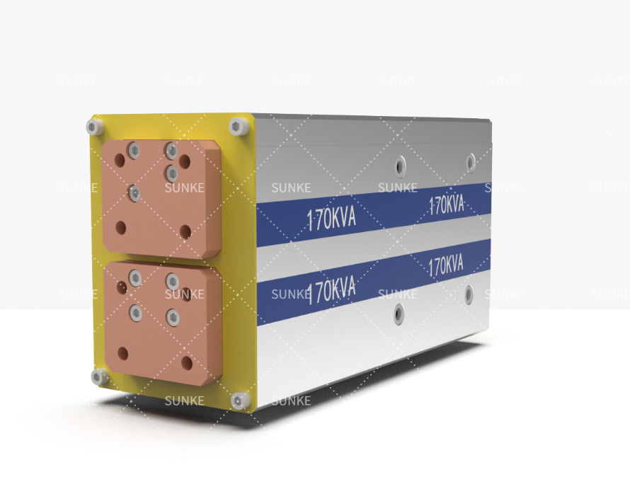
Opening the problem
You pick a transformer wrong, the weld shows porosity, the line stops. This problem-driven piece cuts straight. Many shops chase specs without seeing the real needs. From my time on the shop floor and service calls, the same errors repeat. If you want reliable outcomes, start by matching application to equipment — not the other way round. For many, that means reading beyond brochures and asking suppliers about on-site performance with resistance welding solutions and real duty cycles for their resistance welding equipment.
Why the wrong transformer matters
Bad choice shows quickly. Weak nugget. Excessive spatter. Coil overheating. These affect throughput and quality. Big plants feel it: automotive assembly lines in Detroit measure cost per bad joint in minutes lost. You lose more than metal — you lose predictable output and customer trust. Fixing this begins with recognising the precise problem you face, not the prettiest spec sheet.
Top selection mistakes (and how they break your process)
Here are the recurring mistakes I see, plain and clear.
- Underestimating duty cycle: Transformers run hot if duty cycle exceeds rating. Result: insulation failure and downtime.
- Using a one-size-fits-all KVA rating: Bigger KVA doesn’t always mean better welds. Wrong impedance, wrong control of current.
- Ignoring secondary impedance and lead losses: Voltage drop at electrode ends kills weld consistency.
- Forgetting the electrode force and clamp compatibility: Even a perfect transformer fails with poor mechanical setup.
- Skipping transient response specs: Fast pulse profiles need transformers that settle quickly; otherwise energy distribution is wrong.
How to avoid these mistakes — practical checks
Do these steps before you buy.
- Define the joint and cycle: State the material mix, thickness, and the per-joint cycle time. Be specific.
- Calculate required current and energy, then match to transformer KVA and impedance. Ask for measured secondary current curves, not just theoretical numbers.
- Specify duty cycle with ambient conditions. If duty >50% over a shift, choose higher thermal class and ventilation.
- Measure lead resistance in your layout. Keep secondary leads short and use low-resistance conductors to preserve current shape.
- Confirm mechanical integration: electrode holders, force sensors, and cooling routes must match transformer capabilities.
- Request on-site performance examples from the supplier. Real performance beats lab claims.
Quick troubleshooting when welds go bad
When defects appear, check these in order.
- Secondary current waveform — is it flat or drooping?
- Electrode condition and force — worn tips or wrong pressure spoil joints.
- Transformer temperature — thermal creeping shows rating mismatch.
- Lead connections and contact resistance — loose joints introduce unexpected drops.
- Control timing — delays or jitter change energy delivered to the weld.
Choosing suppliers and validating performance
Do not accept paper-only proofs. Ask for field reports or references for similar applications. Speak to someone who installed and still runs the system. Look for suppliers who document thermal margins and provide measured secondary current traces. That proves they understand the operational side, not just the component specs.
Final synthesis
Pick a transformer by matching duty, current shape, and mechanical environment. Check lead resistance, verify on-site examples, and test under real cycle conditions. These straightforward steps cut cost and downtime. For shops wanting a practical partner that understands these specifics, many teams find value in working with manufacturers who demonstrate measured field performance and clear thermal margins like Sunke.