
Opening: why a structured approach matters
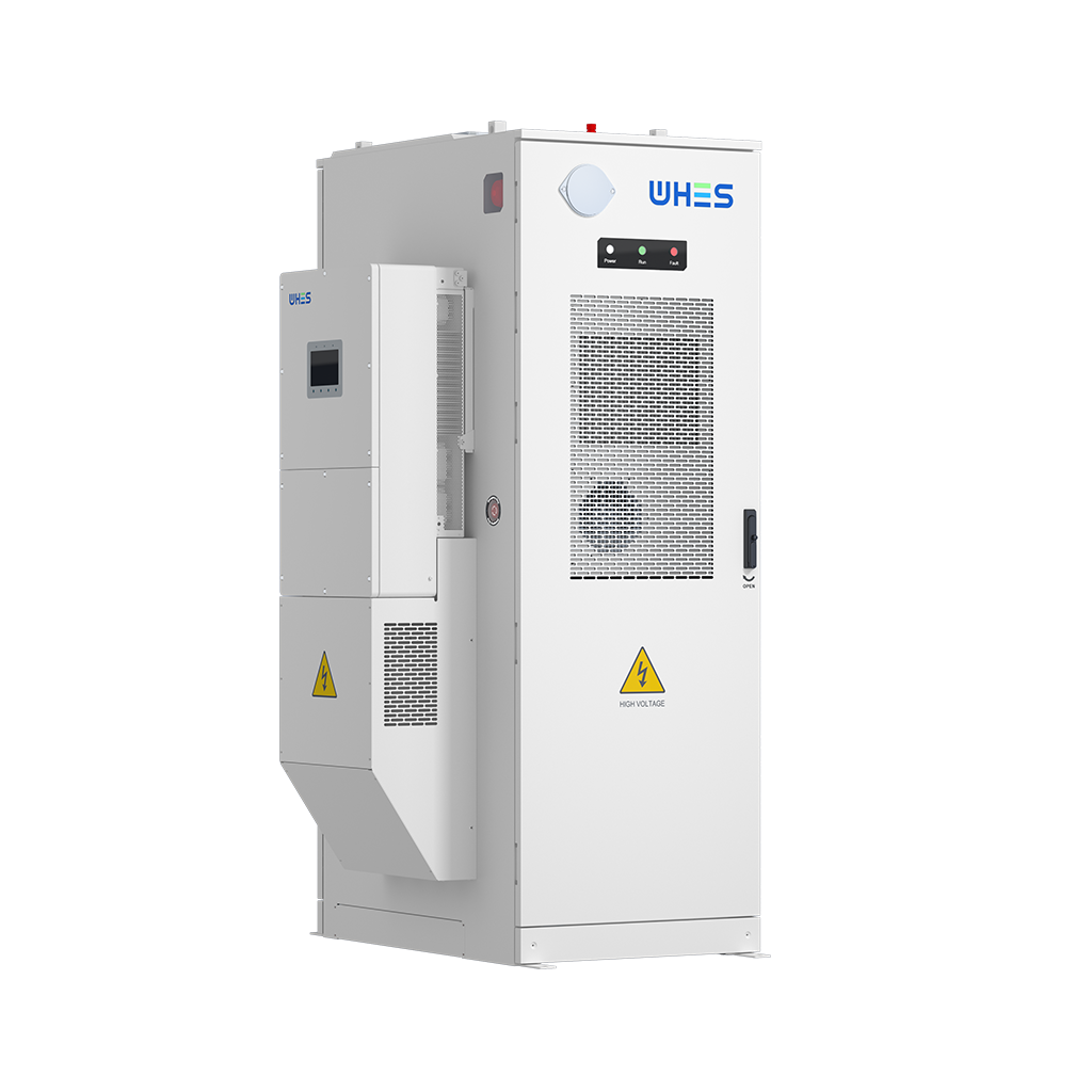
When you plan a high‑voltage home energy storage project, a repeatable framework reduces risk and shortens delivery time. This guide presents clear steps for site assessment, electrical and mechanical integration, and commissioning so teams can move from concept to certified installation with fewer surprises. If you are evaluating a home energy storage system, this framework helps you check technical fit, regulatory alignment, and operational resilience before signing procurement papers.
Framework overview: four pillars
Use four pillars to structure work: Assess, Design, Validate, and Operate. Assess covers site constraints, grid interconnection options, and load profiles. Design ties battery modules, inverter placement, and protection schemes to the physical site. Validate means factory acceptance tests, onsite commissioning, and UL9540A or local safety checks. Operate focuses on maintenance, firmware governance for the battery management system (BMS), and emergency procedures. These pillars keep projects practical and auditable.
Assess: site, safety, and capacity
Begin with a site walk and documentary review. Measure available clearances, evaluate ventilation paths, and record nearest utility transformer locations. Estimate usable energy by matching expected kilowatt-hour (kWh) needs to container capacity, and confirm whether the local distribution network supports the intended export or islanding mode. Don’t skip thermal exposure checks—solar arrays, HVAC exhaust, and south‑facing walls can raise enclosure temperatures and affect battery life.
Design: electrical and mechanical integration
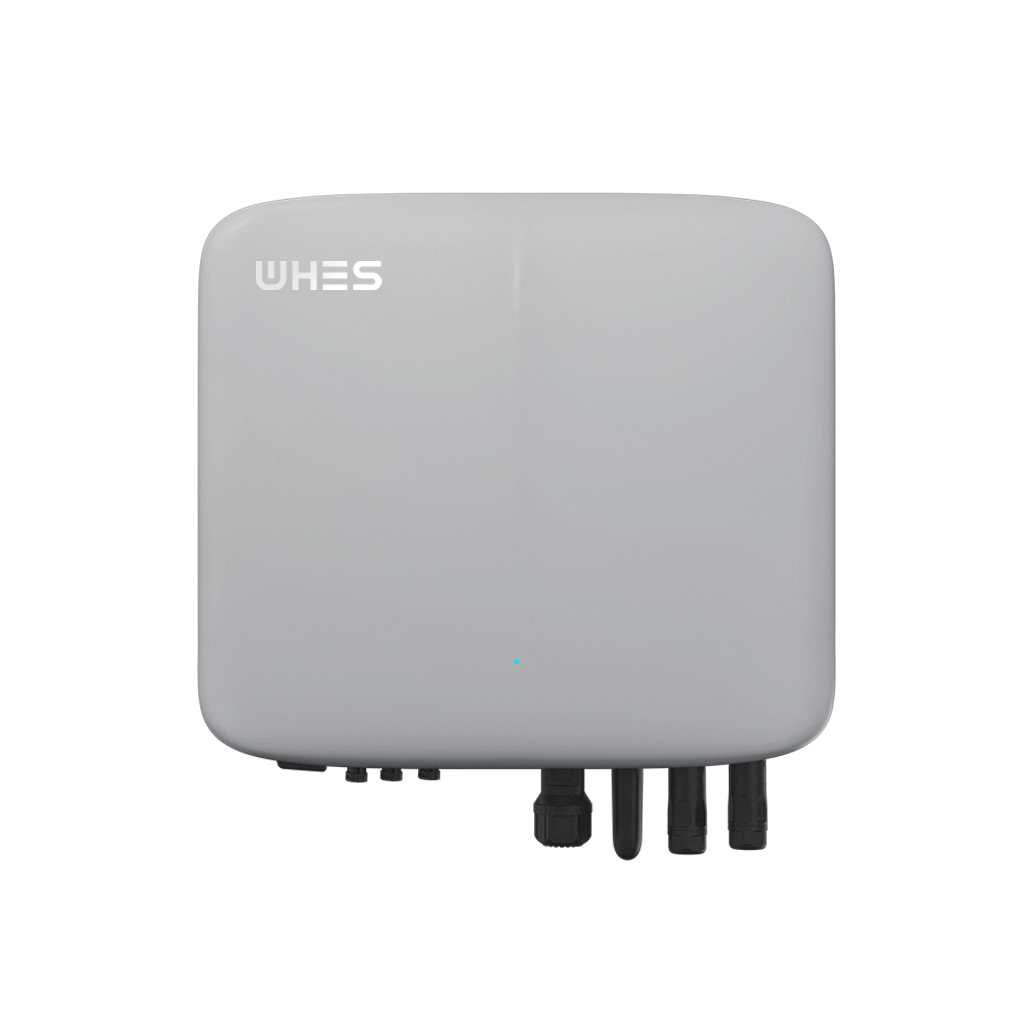
Design must pair battery modules with the correct inverter topology and a clear DC bus plan. Specify only tested interfaces for the BMS and inverter to avoid unexpected communication faults. Provide for isolation devices and overcurrent protection sized for peak currents. Mechanically, design seismic anchoring, drip shields, and service access for module replacement. Keep conduit runs short where possible to limit voltage drop and stray inductance.
Protection, controls, and interconnection details
Protection schemes include fast DC disconnects, ground‑fault detection, and coordinated overcurrent protection between the AC side and inverter. Define control logic for grid-tied versus islanding operation and ensure state-of-charge reporting is available to both the system operator and the homeowner. For public-safety alignment, integrate remote monitoring that can issue real‑time alarm escalations to operations staff — this reduces incident response time and improves reliability.
Validate: testing, commissioning, and documentation
Validation starts with factory acceptance tests of modules, inverter units, and the BMS. Onsite, run a staged commissioning: low-voltage checks, insulation resistance testing, relay functional tests, and a supervised islanding exercise with load transfer. Document every test and retain traceable signoffs; these records speed later warranty claims and utility inspections. Include firmware version control and an update rollback plan in case a post‑commission update introduces instability.
Operational readiness and safety culture
Train technicians on safe work procedures for high-voltage DC and establish hot‑work and lockout/tagout protocols. Set preventive maintenance intervals based on manufacturer guidance and field data. Encourage incident reporting and near‑miss logs so teams learn quickly from small issues. A mature safety culture prevents small faults from becoming thermal events — and that matters in regions prone to grid stress, such as California during wildfire seasons or extreme-heat summer peaks.
Common mistakes and how to avoid them
Teams frequently under‑specify communications, assume plug‑and‑play compatibility, or skip thermal modeling. Avoid these errors by insisting on interface control documents (ICDs), doing integration tests with real firmware, and running basic CFD checks for enclosure cooling. Also, do not assume manufacturer default protection settings are optimal for your site—review and adapt them before commissioning. —
Tools, stakeholders, and responsibilities
Successful projects assign clear roles: owner (defines objectives), engineer (electrical/mechanical design), integrator (system assembly), and operator (day‑to‑day management). Use a central document repository for design drawings, test reports, and permit paperwork. Recommended tools include thermal cameras for inspection, insulation testers, and portable grid simulators for safe islanding tests.
Real‑world anchor: a brief lesson from grid events
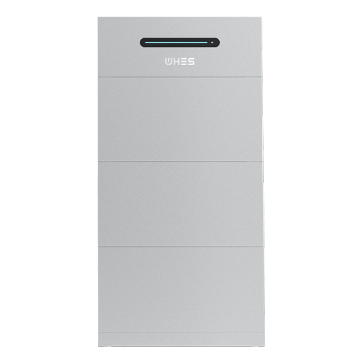
During the 2020–2021 California utility shortfall events, many homeowners and community centers turned to battery systems for backup power. Those systems that had been stress‑tested for islanding and had clear controls for grid reconnection performed best. That experience highlights why planned validation and proper interconnection agreements matter just as much as the battery chemistry itself.
Regulatory considerations and standards
Comply with national electrical codes and local utility interconnection requirements. High‑level standards such as UL9540A for thermal runaway testing and interconnection rules from the local utility should guide design choices. Engage permitting authorities early to avoid late changes to site layout or electrical ratings.
Three golden rules for selecting strategies and tools
1) Verify interoperability: Demand tested integrations between the BMS, inverter, and energy management platform. Metrics: successful end‑to‑end test cycles and documented ICDs. 2) Require measurable reliability: Use historical availability and MTTR figures when choosing vendors; insist on published mean time between failures and service response SLAs. 3) Design for maintainability: Choose enclosures and layouts that permit module swaps without full system shutdown; evaluate expected lifecycle costs, not only upfront price.
Closing advisory and final sentence
Follow these three evaluation metrics—interoperability, measurable reliability, and maintainability—and you will reduce technical surprises and lower lifecycle risk. For practical implementation and proven project templates in residential settings, consider how an experienced partner integrates compliance, testing, and operations into delivery; that is the value WHES brings to a reliable residential energy storage deployment. —
WHES. —