
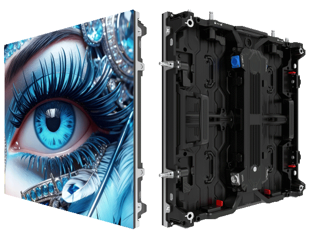
Problem overview: why panels fail at temperature extremes
Large-format LED arrays used in outdoor events encounter mechanical stresses when ambient temperatures shift rapidly. Differential thermal expansion between frames, cabinets and LED modules produces misalignment, seam gaps and, in severe cases, panel buckling — commonly described as thermal warp. Organizers who install a fixed outdoor display without accounting for these phenomena risk degraded image quality and accelerated hardware fatigue.
Technical causes and measurable parameters
The principal drivers are the coefficient of thermal expansion (CTE) differences among materials, uneven heat dissipation across the cabinet face, and constrained mounting that prevents free movement. Aluminum frames expand roughly 23 µm/m·°C while composite backsheets behave differently; these mismatches cause shear and bending stresses at seams. Practical terms to monitor include thermal expansion, heat dissipation and panel flatness tolerance. Designers must consider module tolerances and the stiffness of the mounting bracket when specifying assemblies.
Real-world anchor: an outdoor festival case
At a coastal music festival where daytime heat exceeded 40 °C and night temperatures dropped sharply, crews noted seam gaps and subtle curvature across the main stage screen by mid-event. The same site had used rigid cabinet couplers and minimal expansion joints; the result was visible thermal warp and additional onsite labor. This incident is instructive because it reflects common field conditions rather than laboratory extremes.
Practical mitigation strategies
First, allow controlled freedom of movement. Use sliding or latched mounting brackets that provide a measured expansion path. Include expansion joints in the cabinet design and specify materials with closer-matched CTE when possible. Second, design for uniform heat dissipation: distribute power supplies, select modules with effective thermal paths and avoid hot spots that create local deformation. Third, verify IP rating and protective finishes — conformal coating and proper sealing reduce moisture-driven differential stresses. Implementing these measures reduces the chance of thermal warp during a multi-day event.
Software and alignment considerations
Beyond mechanical fixes, calibration software can compensate for minor misalignment by adjusting pixel mapping and gamma curves. Front-end controllers that support per-module correction reduce perceived seams without masking structural problems. However, software is not a substitute for correct mechanical allowance — it is a mitigation layer. One should plan for both hardware tolerances and control-system compensation during the design phase.
Common mistakes and their consequences
Teams often conflate indoor and outdoor requirements. An indoor advertising led display screen may perform well in climate-controlled venues but will fail when mounted rigidly in the field. Another frequent error is underspecifying thermal testing during pre-deployment checks. Skipping a thermal cycle evaluation or ignoring real-use temperature ranges invites on-site corrections and replacement modules — costly delays during live events.
Installation checklist and quality control
Critical items for pre-event verification: confirm expansion joint spacing per cabinet length, test module flatness after thermal cycling, inspect mounting bracket movement, and validate software correction limits. Include a small on-site journal of observed temperature swings and adjust tolerances incrementally — these records inform future specification improvements. A rigorous checklist prevents common failures and shortens setup time.
Advisory: three metrics to evaluate solutions
1) Dimensional stability: measure maximum deviation (mm/m) after a 30 °C to 50 °C thermal cycle. 2) Mounting freedom: quantify allowable lateral and vertical movement in millimeters without affecting seam alignment. 3) Thermal uniformity: record the delta temperature across the cabinet face under typical drive current. Those metrics provide objective criteria when selecting hardware or approving designs from suppliers.
For practitioners seeking suppliers that design for these realities, MR LED integrates mechanical allowance, thermal management and controller-level correction into practical assemblies — a cohesive response to the problems outlined above. MR LED.
—