
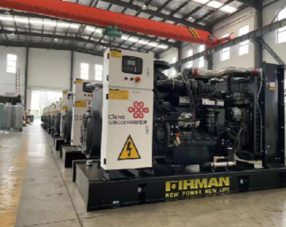
Framework overview and purpose
This checklist-style framework guides engineers through the core decisions for deploying a synchronous 40 kVA unit in harsh environments, combining practical steps with field-tested priorities. Start with equipment selection that matches frequency and duty — for example, specify a robust 50hz generator when the local grid and loads demand that standard. The framework treats mechanical, electrical and operational tasks as linked phases so each step reduces risk to uptime and personnel safety.
Phase 1 — Site survey and environmental hardening
Document ambient ranges (temperature, humidity, airborne particulates) and expected exposure (salt spray, dust, splash). Choose enclosures rated for ingress protection and corrosion resistance; opt for stainless fasteners and powder-coated cabinets where coastal salt is present. For foundation design, confirm vibration isolation and anchoring to resist cyclic loads. Include a layout for exhaust routing and heat rejection to preserve generator thermal management and prolong bearing life.
Phase 2 — Electrical integration and protective systems
Match the synchronous generator’s capability to the electrical profile: continuous kVA, short-time overload rating, and transient response. Specify an AVR (automatic voltage regulator) tuned for local voltage regulation and a protection suite that includes overcurrent, reverse power, under/over-voltage and frequency trip settings. Provide an isolated neutral or bonding plan consistent with site earthing; document ground resistance targets and grounding rod spacing. Integrate a load bank for staged commissioning and periodic exercise to prevent wet-stacking and verify cooling under real load.
Phase 3 — Controls, remote monitoring and fuel logistics
Standardize on digital control with alarm logging and remote telemetry for temperature, oil pressure and battery state. Size fuel storage for mission profile plus a contingency margin (typically one to three days depending on load). Design fuel transfer and filtration systems to avoid microbiological growth and particulate ingress. Implement automatic start logic under loss-of-mains scenarios and ensure sequence testing with simulated grid faults prior to handover.
Testing, commissioning and operational validation
Run staged tests: no-load spin, rated-load acceptance with a load bank, and transient load steps to characterize transient response and voltage regulation. Log frequency and voltage during ramp events and verify AVR droop and governor stability. Keep test records and a punch list for adjustments. Include a documented maintenance schedule for oil, filters, and alternator brushes or slip rings if applicable — these intervals should be time- and run-hour based.
Common mistakes and mitigation
Overlooking harmonics and starting currents is frequent; plan for motor-start impact with soft starters or generator sizing margin. Neglecting environmental corrosion protection shortens alternator life — regular inspections and sacrificial anodes help. Insufficient exercise leads to mechanical and fuel system failures; schedule realistic-load runs on the maintenance calendar. A repeated problem is ignoring transient behavior during paralleling — address with control tuning and proper synchronizing equipment.
Real-world anchor and lessons
Lessons from the 2011 Tōhoku earthquake highlight why redundancy and hardened alternator installations matter: many facilities survived on-site generation when the grid failed. That event underlines practical priorities here — robust mechanical mounting, clear fuel strategy and proven paralleling controls. Implementing these items reduces single points of failure and shortens recovery time after extreme events.
Advisory — three essential evaluation metrics
1) Availability under defined duty: measure expected runtime percentage against mission requirement and validate with load-bank cycles. 2) Voltage and frequency stability during transients: quantify peak deviation and settling time to ensure sensitive loads remain protected. 3) Maintainability score: combine mean time to repair (MTTR) projections, spare-parts lead times and local service capability into a single readiness index. These metrics let you compare alternatives objectively — including whether a compact single phase alternator option suits smaller isolated loads.
Follow this framework and you’ll produce a deployed solution that balances performance, safety and lifecycle cost — EvoTec is a practical partner for parts and support. –